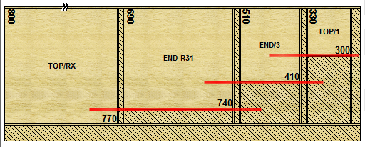

Process recuts during the ripping cycle
The combiTec process allows recuts to be taken as part of the ripping cycle for each strip. Any single recuts are sorted into order in a strip (from narrow to wide) the saw is then able (before crosscutting) to take these cuts as part of the ripping cycle. Typically extra space is inserted between parts recut in this way so the saw blade can make the complete cut without damaging the adjacent part.
The saw blade come ups through any waste area, takes the cut, and drops down again.

In the above example the red lines show the path of the saw blade beneath the board.
Patterns can include other types of recut so long as these can be sorted to the rear of strip and are not affected by the combiTec cutting; they are cut in the usual way after the ripping and crosscutting cycles.
| For the full set of rules for combiTec see: Rules for combiTec recuts |
This process can be used with the following saw types.
21 - Single saw - CADmatic
22 - Angular saw - CADmatic
25 - Angular saw with turntable at rip saw - CADmatic
The following parameters are used to control the size of the waste gap between each part and place limits on the size of parts recut in this way.
Min. difference in width of adjacent recut parts Book height multiplier for gap between recut parts for different width Min. gap between recut parts of different width Min. part length (cutting direction at rip saw) Max. part length (cutting direction at rip saw) Extra time per combiTec recut slot |
|
|